Bucket Elevator Design: Capacity Calculation, Bucket Size, Speed & Motor Power
A bucket elevator looks simple — buckets on a belt or chain, moving material up. The engineering behind sizing one correctly isn't simple at all: get the bucket size, speed, or motor power wrong, and you end up with an elevator that either can't hit the required throughput or trips its motor overload within the first week.
This is a working guide to the actual calculations — capacity, bucket sizing, speed, and power — that go into designing a bucket elevator correctly, with a worked example at the end.
1. What is bucket elevator design?
Bucket elevator design is the process of sizing every component of the elevator — bucket volume and spacing, belt or chain speed, casing dimensions, and motor/gearbox rating — against three inputs: the material's bulk density and flow characteristics, the required capacity (TPH), and the lifting height. Design isn't a single calculation; it's a sequence, where each output (say, bucket spacing) becomes an input to the next step (speed, then power). Getting the sequence right, in order, is what separates a properly engineered elevator from a catalogue-sized one.
2. Bucket elevator design parameters
Every design calculation traces back to five core parameters:
- Material bulk density (t/m³ or kg/litre)
- Required capacity (TPH — tonnes per hour)
- Lifting height (metres, boot centerline to head discharge)
- Bucket volume and spacing (litres, and pitch in metres)
- Belt or chain speed (m/s)
Everything else — motor power, casing size, drive selection — is derived from these five once they're fixed.
3. How to calculate bucket elevator capacity
Capacity is a function of how much material each bucket carries, how often a bucket discharges, and how efficiently the buckets actually fill:
Q (TPH) = (v / S) × V × ρ × FF × 3.6
Where:
- Q = capacity in tonnes per hour
- v = belt/chain speed (m/s)
- S = bucket spacing/pitch (m)
- V = individual bucket volume (litres)
- ρ = material bulk density (kg/litre — numerically equal to t/m³)
- FF = fill factor (typically 0.75–0.85 for centrifugal discharge, 0.85–0.95 for continuous discharge)
This single formula is the backbone of the rest of the design — once required capacity is fixed, you're solving for the combination of bucket volume, spacing, and speed that satisfies it.
4. Bucket size and bucket spacing
Bucket volume and spacing work together, not independently. Wider or deeper buckets carry more material per cycle, letting you run at lower speed for the same capacity — generally preferable, since lower speed reduces wear and impact loading at discharge. Tighter spacing increases the number of buckets discharging per minute, achieving the same effect from the opposite direction.
As a practical starting point: bucket width is typically sized between 65% and 80% of casing internal width, and spacing (pitch) is set so buckets don't interfere with each other while filling at the boot — usually 1.5 to 3 times the bucket projection, depending on discharge type.
5. Bucket elevator belt speed
Belt-type centrifugal elevators typically run between 1.0 and 2.0 m/s. Speed here isn't arbitrary — it has to be fast enough that centrifugal force actually throws material clear of the bucket at the head pulley, but not so fast that it creates excess bucket impact and belt wear. Running below the minimum speed needed for clean centrifugal discharge causes material to dribble back down inside the casing instead of clearing into the discharge chute — a common cause of reduced effective capacity that looks like a bucket sizing problem but is actually a speed problem.
6. Bucket elevator chain speed
Chain-driven, continuous discharge elevators run considerably slower — typically 0.4 to 1.0 m/s — because continuous discharge relies on gentle tipping as buckets round the head sprocket, not centrifugal force. Running a continuous-discharge elevator too fast defeats the purpose of choosing that discharge type in the first place, since impact-driven discharge at speed causes the same material degradation continuous discharge is meant to avoid.
7. How to calculate bucket elevator power
Power requirement starts from the basic physics of lifting mass against gravity, then adds efficiency losses:
P (kW) = (Q × H) / (367 × η)
Where:
- Q = capacity (TPH)
- H = lifting height (m)
- η = mechanical efficiency (typically 0.75–0.85, accounting for friction losses in bearings, belt/chain, and drive)
This gives the theoretical running power. Actual motor selection then adds a safety margin for starting torque and boot pickup resistance — covered next.
8. Motor and gearbox selection
The calculated running power from Step 7 is not the number you buy a motor against. Motor selection needs to account for:
- Starting torque — an elevator starting under a fully loaded boot needs significantly more torque than running power alone suggests, which is why a safety factor of roughly 1.3–1.5× the calculated running power is standard practice
- Standard motor sizing — round up to the next standard motor rating (e.g., a calculated 3.7 kW requirement typically moves to a 5.5 kW motor), since custom motor windings for a non-standard rating add cost without benefit
- Gearbox reduction ratio — sized to deliver the exact belt/chain speed calculated in Steps 5–6 from standard motor RPM
- Backstop device — essential on any elevator with meaningful lift height, to prevent the loaded belt or chain running backward if power is lost mid-operation
9. Elevator height and lift capacity
Height doesn't just add to power requirement linearly — it also drives structural decisions. Beyond roughly 15–20 metres, belt-type elevators generally need intermediate casing supports to control belt sway, and chain-type elevators need to confirm chain tensile rating against the added dead weight of a longer chain run. Bucket elevators can be engineered up to around 40 metres of lift, but every additional few metres beyond 20m is worth a specific structural check rather than assuming the same casing design scales indefinitely.
10. Centrifugal vs. continuous bucket elevator design
The two discharge types aren't just different bucket shapes — they represent different design philosophies:
- Centrifugal discharge — higher speed, spaced buckets, throws material clear using centrifugal force. Simpler design, lower cost, suited to free-flowing, non-fragile material.
- Continuous discharge — lower speed, closely spaced (often overlapping) buckets, material spills from bucket to bucket via a guide plate. More complex casing geometry at the head, but essential for fragile, abrasive, or high-density material that centrifugal throwing would damage or that wouldn't discharge cleanly at higher speed.
Discharge type should be chosen before bucket sizing begins, since it changes both the speed range (Steps 5–6) and the fill factor assumption (Step 3).
11. How material bulk density affects design
Bulk density feeds directly into the capacity formula (Step 3), but its effect goes further: denser materials increase bucket loading (and therefore torque and power) faster than volume alone suggests, which is why two materials with identical required TPH but different bulk density can need meaningfully different bucket sizes, belt ratings, and motor power. A design calculated against an assumed or generic bulk density figure, rather than the material's actual tested value, is one of the most common sources of underpowered elevators in the field.
12. Effect of moisture, particle size, and material flowability
Bulk density and TPH cover the arithmetic, but three additional material characteristics change how the elevator behaves in practice:
- Moisture content — increases the risk of material sticking to bucket walls instead of discharging cleanly, particularly in centrifugal designs; high-moisture material sometimes needs continuous discharge even when density and particle size alone would suggest centrifugal
- Particle size — large or irregular particles reduce effective fill factor, since they pack less efficiently into a bucket than fine, uniform material
- Flowability — cohesive or sticky materials require larger bucket spacing and often a different bucket profile (deeper, steeper leading edge) to fill and empty reliably
None of these show up in the core formulas directly — they show up as adjustments to fill factor and discharge type selection.
13. Belt vs. chain bucket elevator
Belt and chain aren't interchangeable design choices — they're suited to different operating envelopes. Belt-type construction is lower cost, lighter, and suited to ambient-temperature, moderately abrasive material up to roughly 80°C. Chain-type construction, using forged steel chain, handles higher temperatures (up to roughly 250°C) and more abrasive or heavier material, at higher capital cost. (For a full mechanical breakdown of belt-type design — belt selection, bucket attachment, splicing, and tracking — see our dedicated guide: Belt Bucket Elevator Conveyor Manufacturer in India.)
14. Bucket elevator casing design
The casing isn't just an enclosure — it's a structural and containment component. Casing thickness is typically specified between 3mm and 6mm depending on material abrasiveness, with reinforcement at the head and boot sections where mechanical stress concentrates. Casing joints need properly sealed gaskets, both to contain dust (a compliance requirement in many plants) and to prevent moisture ingress on hygroscopic materials like fertilizer. Inspection doors along the casing length are a design requirement, not an optional extra — without them, a mid-section belt or bucket issue is effectively undiagnosable without full disassembly.
15. Boot and head section design
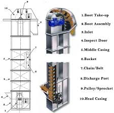
The boot section — where material is picked up — needs a properly sized take-up device to maintain correct belt or chain tension, plus a boot design that avoids material accumulation ("boot flooding") if the elevator is stopped while still loaded. The head section houses the drive pulley or sprocket, and must be sized to give buckets enough clearance to fully round the discharge point without buckets striking the casing — a clearance calculation directly tied to bucket size and casing width from Step 4.
16. Bucket elevator discharge design
Discharge geometry is discharge-type dependent. Centrifugal elevators need a discharge chute positioned to catch material at the exact angle it's thrown from the bucket at the top of its arc — a geometry calculated from bucket speed and head pulley diameter, not guessed. Continuous discharge elevators instead use a guide plate that channels material from each bucket into the one behind it as it rounds the head sprocket, requiring closer manufacturing tolerance on bucket spacing than centrifugal design does.
17. Example bucket elevator design calculation
Worked example: a grain (wheat) bucket elevator, required capacity 45 TPH, lift height 15 m.
Inputs:
- Bulk density (wheat): 0.75 t/m³ = 0.75 kg/litre
- Bucket volume: 4.5 litres
- Bucket spacing: 0.3 m
- Belt speed: 1.5 m/s
- Fill factor: 0.80 (centrifugal discharge)
- Mechanical efficiency: 0.80
Step 1 — Capacity check: Q = (v/S) × V × ρ × FF × 3.6 Q = (1.5/0.3) × 4.5 × 0.75 × 0.80 × 3.6 Q = 5 × 4.5 × 0.75 × 0.80 × 3.6 ≈ 48.6 TPH
This comfortably clears the 45 TPH requirement, confirming the bucket/spacing/speed combination is adequate.
Step 2 — Power calculation: P = (Q × H) / (367 × η) P = (48.6 × 15) / (367 × 0.80) P = 729 / 293.6 ≈ 2.48 kW theoretical running power
Step 3 — Motor selection: Apply a 1.5× starting-torque safety factor: 2.48 × 1.5 ≈ 3.7 kW → round up to the next standard motor rating, typically 5.5 kW, with gearbox ratio selected to deliver the 1.5 m/s belt speed from the motor's rated output RPM.
This example is illustrative — real designs should also account for boot pickup resistance and specific belt/chain friction losses, which is why final sizing should always be confirmed by the manufacturer against your exact material test data.
18. Bucket elevator design checklist
- Material bulk density confirmed from actual test data, not assumed
- Required capacity (TPH) and lifting height fixed
- Discharge type selected (centrifugal or continuous) based on material fragility/abrasiveness
- Bucket volume and spacing sized against capacity formula
- Belt or chain speed within correct range for discharge type
- Fill factor assumption adjusted for moisture, particle size, and flowability
- Motor power calculated with starting-torque safety factor applied
- Casing thickness specified against material abrasiveness
- Inspection doors included at head, boot, and mid-casing sections
- Backstop device included for loaded-belt safety
19. How to select a bucket elevator manufacturer
Once the design calculations above are in hand, the manufacturer conversation should confirm they're doing this same engineering — not quoting a standard size regardless of your inputs. For the full vetting checklist covering component quality, customisation, after-sales support, and compliance, see our dedicated guide: Bucket Elevators Explained: Types, Components & How to Choose the Right Manufacturer.
20. FAQ
Do I need to do these calculations myself before contacting a manufacturer? No — but knowing your material's bulk density, required TPH, and lift height lets you evaluate whether a manufacturer's quote is actually engineered for your application or just a standard size.
What's a reasonable fill factor to assume if I don't have exact data? 0.75–0.80 for centrifugal discharge and free-flowing material is a safe starting estimate; continuous discharge with well-behaved material can run higher, up to 0.90–0.95.
Why does my calculated capacity not match what the elevator delivers in practice? The most common causes are running below the minimum speed needed for clean discharge (Step 5), an overly optimistic fill factor assumption, or bulk density that differs from the design value due to moisture content.
Is a higher motor safety factor always safer? Not necessarily — significant over-sizing increases capital cost and can cause the motor to run inefficiently at partial load. The 1.3–1.5× range is a practical balance, not a "bigger is always better" rule.
Final thoughts
Bucket elevator design is a sequence — bulk density and required capacity define bucket size and speed, which together define power, which defines the motor and gearbox. Skipping a step, or assuming a generic value where a real material figure should be used, is where most underperforming elevators originate.
Neo Conveyors engineers bucket elevators from your actual material data through this full design sequence, rather than selecting from a fixed size chart. Send your material and capacity requirements for a free design calculation.
Related reading
Recent Posts